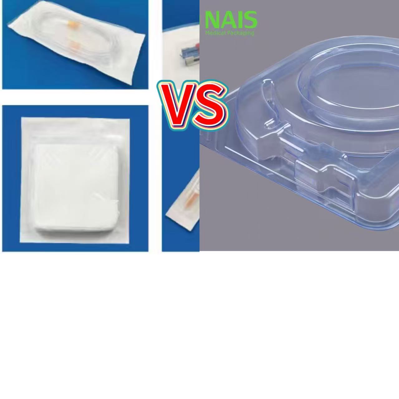
Automatic Soft Thermoforming Packaging Line: Seven Critical Stages in the Forming Process
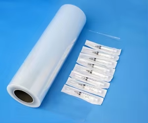
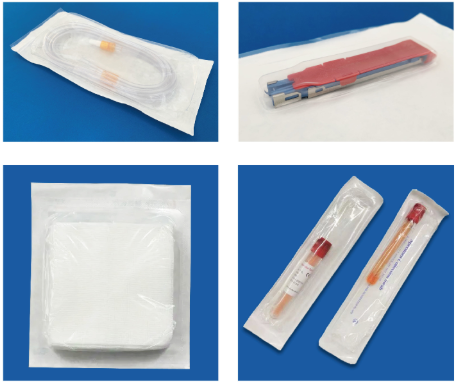
In a medical consumables production area, an automatic soft blister packaging line in operation appears to be a continuous process of “film in, bags out.” However, to ensure that products such as gauze pads, syringes, IV sets, and catheters are securely enclosed within a sterile barrier, the entire line must simultaneously maintain the process window at seven critical stages. If any one of these points deviates, the result will be either defective pouches or products with potential sterilization failures.
Below, we’ll break down these seven critical points based on the actual material flow of a production line.
Critical Point 1: Base Film Unwinding and Constant Tension Control
The base film for soft thermoforming is fed onto the machine in roll form—typically a PE-based multilayer co-extruded film with a thickness of 0.1–0.3 mm. This is completely different from the sheet feeding process in rigid thermoforming—where sheets are fed individually—as soft film is fed continuously, making it at least one order of magnitude more sensitive to tension.
If tension is unstable, all subsequent stations will be affected: the film surface will undulate in the heating zone, leading to uneven heating; inconsistent stretching during forming will result in uncontrolled cavity wall thickness; and material misalignment during heat sealing will cause uneven seal widths.
On-site experience: The unwind braking device must be paired with constant tension feedback, along with a film guide frame and silicone pressure strips; otherwise, thin dialysis paper or flexible medical composite films are highly prone to material deviation and creasing at high speeds, which can cause them to jam directly between the heat-sealing blade and the cutting module.
The compatibility of molds and accessories is equally important: if the corners of universal molds lack rounded transitions, demolding resistance will be high after thermoforming; if film guide frames and silicone pressure strips lack sufficient wear resistance, they will deform or shed particles after short-term use, hindering the smooth transport of the film material.
Challenge 2: Heating and Softening—Temperature Differences Must Be Kept Within ±5°C
As the soft film passes between the upper and lower heating plates, infrared or cast aluminum heating plates heat it to a malleable state. The key to this step is uniformity.
For PE-based soft film, the heating temperature depends on the material properties, with the goal being to make the film soft and elastic without causing it to flow. However, what truly determines success or failure is the temperature difference across the heating surface—conventional heating plates generate heat at a single point, resulting in a surface temperature difference of up to ±8°C. In low-temperature areas, insufficient fusion leads to a false seal, while in high-temperature areas, the dialysis paper carbonizes and becomes brittle and cracks.
Therefore, professional medical thermoforming equipment performs three key functions:
⑴Zoned heating control: Divides the work area into multiple independent temperature zones based on the film width to compensate for heat loss at the edges
⑵Real-time infrared temperature monitoring: Uses an infrared thermometer to monitor temperature, ensuring a temperature difference of ≤±5°C
⑶Two-stage heating (preheating + forming): Preheat first, then raise to the forming temperature
The consequences of uneven heating only become apparent at the forming station: Locally excessive film temperature → excessive thinning during stretching → sharp reduction in cavity bottom wall thickness → perforation after sterilization; insufficient local temperature → insufficient stretching → shallow cavity → product cannot be loaded or the dialysis paper is pushed against during sealing.
Challenge 3: Vacuum/Positive Pressure Forming—Pressure Differential Is the Driving Force, Venting Is the Art
The softened membrane is step-fed to the forming station; this moment—lasting 1–3 seconds—is the most critical part of the entire production line.
Basic Principle: A vacuum is applied to the mold side, while atmospheric pressure is maintained above the membrane; a pressure difference of approximately 0.1 MPa forces the membrane to conform to the mold. The vacuum level typically needs to reach -0.08 to -0.1 MPa.
Direct Vacuum Suction for Shallow Cavities: For shallow cavities (< 20 mm), such as dressings and gauze pads, simple vacuum suction is sufficient, with a forming time of 3–5 seconds.
Deep cavities require a “pre-blow + vacuum” combination: When cavity depth exceeds 20 mm, pure vacuum causes the film to become excessively thin at the bottom of the cavity. In this case, pre-form the part at low pressure (e.g., -0.06 MPa), followed by pre-stretching with positive pressure (0.2–0.6 MPa) to blow the bubble, and finally apply full vacuum. This allows the film to stretch uniformly before adhering to the mold, ensuring consistent wall thickness throughout the cavity.
The design of the venting system is where mold manufacturers truly demonstrate their expertise:
Soft PE/PVC sheets: Vent hole diameter 0.25–0.6 mm, hole spacing 8–12 mm
Honeycomb-shaped vent arrays must be installed at the base of R-corners and at the center of flat surfaces
Excessively fast vacuum draw rates may cause material tearing, while excessively slow rates affect molding accuracy; the target vacuum level is generally set to be reached within 2–5 seconds
A severely underestimated detail: vacuum leakage rate. Precision thermoforming requires a vacuum leakage rate of < 0.5 kPa/min; otherwise, pressure will rebound during the pressure-holding stage, causing the cavity to spring back and deform.
Step 4: Cooling and Setting—Fast and Uniform for a Rigid, Full-Bodied Cavity
Many people think the process is over once molding is complete, but in fact, the cooling rate directly determines the cavity’s rigidity and the level of internal stress.
Cooling in soft thermoforming involves two conflicting objectives:
Fast—Production line cycle times require 10–14 cycles per minute, so cooling must be completed within 1–3 seconds
Uniform — To avoid localized cooling inconsistencies that lead to internal stress concentration and the propagation of microcracks during storage and transportation
The mainstream solution involves water-cooling or spray cooling within the mold, with a cooling rate of 5–15°C/s. High-end molds maintain a distance of 8–12 mm between the cooling channels and the mold surface, with water temperature fluctuations of ≤±2°C.
The consequences of insufficient cooling: soft cavities that collapse during subsequent filling; further deformation of the cavities during sterilization, causing the product to rub against the dialysis paper and compromising the aseptic barrier. This is why professional equipment manufacturers emphasize that “high-rigidity molding, combined with precisely controlled heating and molding pressure, ensures that blister shells remain upright and full-bodied, facilitating subsequent cartoning and guaranteeing that products do not shift during transportation, thereby preventing damage to the aseptic barrier caused by friction.”
Challenge 5: Filling—Synchronization Is Everything
After forming, the blister strip is moved step-by-step to the filling station. Solid materials (such as syringes and catheter connectors) fall by gravity into the blister cavities via a vibrating feeder, a belt-type feeder, or a brush-plate feeder; irregularly shaped items or liquids/pastes can be filled using a metering pump or manual assistance.
The critical issue at this station is synchronization. Conventional PLC programs have fixed cycle times, resulting in poor timing alignment between filling, stretching, sealing, and cutting. During high-speed production, this leads to excessive film stretching, feed timing discrepancies (either too early or too late), and frequent overload shutdowns.
Anti-jamming warning mechanisms and servo-driven indexing are the defining features that make the difference. Imported lines (such as Siemens/Omron PLCs + servo drives) can achieve positioning accuracy of ±0.5 mm, whereas mid-range domestic lines often fall short in this regard—manifesting as misaligned fillings, mold jams, and undetected material shortages that go unweeded out, ultimately resulting in defective products being mixed into the finished batch.
The filling station is also the optimal location for deploying a vision inspection system: it checks assembly integrity and automatically rejects defective products. Manufacturers without this step rely almost entirely on manual visual inspection, and the rate of missed defects rises sharply with shift fatigue.
Challenge 6: Heat Sealing of Dialysis Paper—The Final Step in Ensuring the Sterile Barrier
If the first five checkpoints determine “what the bag looks like,” then the heat sealing station determines “whether the bag can maintain sterility.”
The three key elements of heat sealing—temperature, pressure, and time (or speed)—must work in concert.
Temperature
The process design of dialysis paper blister heat-sealing machines is centered on preserving the fiber integrity of the dialysis paper while fully activating the adhesive layer. This prevents excessive temperatures from damaging the paper’s pore structure or insufficient temperatures from causing incomplete fusion of the adhesive layer, which would result in a false seal. Typical equipment has an adjustable sealing temperature range of 80–180°C.
Pressure
The typical pressure range is approximately 0.3–0.6 MPa and must be adjusted linearly according to material thickness. A contouring platen design ensures uniform pressure at complex structures, preventing cold seals or perforations. A pneumatically or servo-driven upper platen applies gentle, uniform pressure to the surface of the dialysis paper.
Time/Speed
High-efficiency models can reduce heat-sealing time to 3–5 seconds. During the pressure-holding phase, pressure must be maintained below the material’s glass transition temperature (Tg) to ensure sufficient cross-linking of the molecular chains.
The three most common failure modes:
| Failure | Symptoms | Root Cause |
| Incomplete Seal | Appearance is intact, but batch-wide leakage occurs after sterilization | Insufficient fusion in low-temperature areas |
| Carbonization and Brittle Fracture | Micro-cracks appear after storage or logistics vibrations | Carbonization and brittle fracture of the dialysis paper in high-temperature areas |
| Seal-edge bubbles/microcracks | Risk of sterile barrier failure | Conventional heating plates generate heat at a single point, resulting in surface temperature differences of up to ±8°C |
Industry data: Over 60% of packaging-related quality issues stem from a lack of precision in the heat-sealing system. This is why medical-grade equipment must use servo-driven heat-sealing mechanisms to ensure uniform and stable sealing force, with burst strength far exceeding industry standards.
Acceptable range for seal strength: Typically required to be ≥1.5 N/15 mm (YY/T 0681.2). If strength is too low → the seal is prone to premature opening, resulting in failure of the sterile barrier; if strength is too high → the material tears and sheds debris during opening, contaminating the product. The appropriate approach is to set upper and lower limits to ensure the strength falls within a range where the seal “neither leaks nor breaks.”
Challenge 7: Coding, Cutting, and In-Line Inspection
After heat sealing is complete, the lot number and expiration date are applied in-line via a coding/embossing device, and then a stepper-driven feed mechanism feeds the continuous blister strip into the die-cutting mold.
The key to the cutting station can be summed up in two words: positioning. The color mark registration system ensures the precise positioning of the cross-cutting blade, resulting in individual packages with neat edges and consistent seal widths. Positioning deviations can lead to inconsistent seal widths, while a heat-sealing zone that is too narrow can cause the adhesive to peel off after aging, thereby compromising the integrity of the aseptic barrier system.
The in-line inspection system (vision inspection system) serves as the final checkpoint at this station: it verifies assembly integrity and seal quality, automatically rejecting defective products. A production line without this process effectively places the entire burden of quality control on final QC spot checks—yet spot checks can never detect 100% of defects.
The Invisible Eighth Checkpoint Spanning All Seven: Process Validation
The seven checkpoints above are those for “routine production.” However, for this system to stand up to regulatory scrutiny, a comprehensive validation system must be in place throughout the entire process.
According to GB/T 19633.2—2024 (equivalent to ISO 11607-2:2019), the validation of the packaging process should follow a three-step approach: IQ → OQ → PQ:
IQ (Installation Qualification): Equipment is correctly installed and calibrated, and key instruments have calibration schedules.
OQ (Operational Qualification): Test sealing within the upper and lower limits of temperature, pressure, and speed, with at least 10 samples per group, to identify the operating window.
PQ (Performance Qualification): Continuous operation under expected production conditions, with at least three production runs covering practical scenarios such as normal startup and shutdown, shift changes, and variations between material batches.
Four core validation steps that cannot be omitted:
Seal integrity test: Dye penetration method (ASTM F1929); no leakage after standing for 5–30 seconds indicates a pass
Seal strength test: YY/T 0681.2; peel rate of (200±10) mm/min; standard requirement ≥1.5 N/15 mm
Sterilization Compatibility Validation: For EO sterilization, breathable Tyvek® is the preferred choice; for gamma/electron beam sterilization, radiation-resistant materials must be selected that do not yellow or become brittle after 25 kGy, with tensile strength loss typically ≤15%
Accelerated Aging + Simulated Transportation: 50–60°C, 50% ± 10% RH to simulate a 2–5-year shelf life; conduct drop, vibration, and stacking tests in accordance with ISTA 2A/3A
Common Pitfalls: Fluctuations in heat-sealing temperature and inconsistent seal widths can result in a batch that appears intact but leaks after sterilization; products that pass testing at room temperature may develop cracked seals or delaminated Tyvek after aging—indicating substandard resistance to moist heat; low-cost, non-medical dialysis paper may remain airtight in the short term, but micro-pores enlarge during long-term storage, leading to failure in sterility testing.
Final Thoughts: Seven Critical Steps—Not a Single One Can Be Overlooked
Back on the factory floor. A well-designed automated soft thermoforming line should look like this:
The base film roll is fed out smoothly at a constant tension → Infrared heating plates evenly soften the film to a malleable state → A vacuum pump reduces the vacuum to below -0.08 MPa within 2–5 seconds, assisted by positive-pressure pre-blowing, the film conforms to the mold for forming → water cooling inside the mold sets the cavity shape within 1–3 seconds → a servo-driven feeder precisely fills the cavity with the product → the dialysis paper and base film are heat-sealed at a pressure of 0.3–0.6 MPa and a temperature of 80–180°C → Coding, color-mark registration, and cutting → Visual inspection to reject defective products → Output of finished products.
Cycle rate: 10–14 cycles per minute, with full PLC + servo + touchscreen HMI control throughout the process; SUS304 stainless steel in contact with the product.
It may appear seamless, but behind every “seemingly natural” motion lies the precise coordination—at the micrometer and millisecond levels—of five variables: temperature, pressure, time, tension, and vacuum level. If any one variable strays outside the specified window, the next second results in a defective pouch—or worse, a sterile barrier that has passed QC, been shipped, and is quietly failing in a hospital warehouse.
This is why medical soft thermoforming production lines “typically use fully automated packaging equipment”: it’s not about showing off technical prowess, but because manual labor simply cannot maintain the process capabilities required at these seven critical control points. Precisely for this reason, conducting IQ/OQ/PQ validation in accordance with ISO 11607 is not a mere “formality” to satisfy regulators, but the only way to truly transform this line into a “sterile barrier production line.”
Flexible Forming Film vs Rigid Thermoform Tray: It's Not Just "Soft vs Hard"
Soft Thermoforming Film: It May Have “Thermoforming” in the Name, but It’s Something Entirely Different at Its Core